Fork disc brake mount dimensions: IS, post mount and flat mount
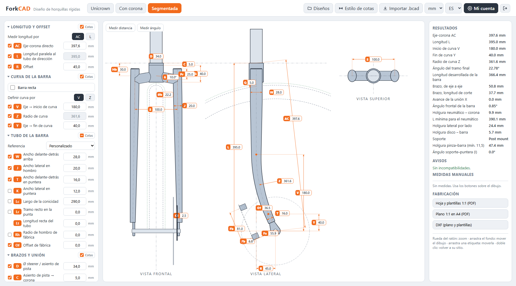
Fork disc brake mounts are located from the wheel axle, with the blade held vertical. An IS mount (160 base) has two holes 51 mm apart, at radii of 49.7 and 87.3 mm from the axle. A post mount has M6 bolts 74.2 mm apart; for a 160 rotor the post face sits at A = 55.9 mm from the axle and the lower hole at B = 6.8 mm. A threaded front flat mount has M5 bolts 70 mm apart, with A = 11 and B = 23.5 mm for 140/160.
Below are the full Shimano and SRAM numbers, how they are measured and how much room they leave for the caliper and the rotor.
How the A and B dimensions are measured
The official Shimano and SRAM drawings dimension everything with the dropout and blade vertical and the wheel axle as the origin:
- A: perpendicular distance from the axle to the plane of the mounting face (the post faces on a post mount, the rear face of the blade on a flat mount).
- B: offset along that face, from the axle to the lower hole.
IS does not use A and B: it gives the radius of each hole from the axle.
IS (International Standard) fork mount, 160 base
| Item | Value |
|---|---|
| Hole spacing | 51 ±0.1 mm |
| Radius, axle → lower hole | 49.7 ±0.1 mm |
| Radius, axle → upper hole | 87.3 ±0.1 mm |
| Holes | Ø6.2 mm, through, unthreaded |
| Maximum angle of the hole line | 24° |
IS hole positions with the blade vertical
From the two radii and the 51 mm spacing, with the blade vertical the holes sit 42.95 mm behind the axle, at heights of 25.0 and 76.0 mm. Shimano does not give these figures directly: they follow from those three figures.
The Shimano drawing places the IS mounting face 4 mm (+1.3/−0.3) from the inner face of the dropout for QR, 15×100 and 15×110 axles.
IS caliper clearance zone
SRAM keeps a Ø60 mm circle clear for the caliper, centred 70 mm behind the axle and 50 mm above it, with the blade vertical. If the blade enters that circle, the caliper hits it.
Larger rotors on an IS fork
The mount geometry stays the same; you add an IS to post mount adapter. Adapter sizes according to SRAM:
| Rotor | Adapter on IS 160 | Adapter on IS 140 |
|---|---|---|
| 160 mm | none | 20 |
| 180 mm | 20 | 40 |
| 200 mm | 40 | — |
| 220 mm | 60 | — |
A 140 IS fork also exists, with its own adapters (right-hand column).
Post mount fork dimensions: bolt spacing, thread and torque
| Item | Value |
|---|---|
| Bolt spacing | 74.2 ±0.1 mm |
| Thread | 2 × M6×1.0, at least 12 mm of full thread |
| Torque the thread must hold | 9.5 N·m |
| Hole line, lateral position | 0.94 mm towards the wheel from the inner face of the dropout (9×100, 15×100, 15×110, 20×110 Boost); 5.94 mm for old 20×110 |
| Maximum angle | 17° |
Post mount A and B by rotor size
A runs from the axle to the plane of the post faces; B runs along that face to the lower hole. Shimano and SRAM agree for 160 and 203 but not for 140 and 180, where they differ by up to 0.6 mm:
| Native rotor | Shimano A / B (mm) | SRAM A / B (mm) |
|---|---|---|
| 140 | 47.5 / 1.7 | 47.24 / 1.8 |
| 160 | 55.9 / 6.8 | 55.9 / 6.8 |
| 180 | 64.0 / 12.4 | 64.56 / 11.8 |
| 200 | — | 73.22 / 16.8 |
| 203 | 73.9 / 18.8 | 73.9 / 18.8 |
| 220 | — | 81.88 / 21.8 |
Since the mount is brazed or welded in a positioning fixture, ForkCAD shows you where it lands on the blade and warns you if the rotor or caliper hits it.
Clearance between the post faces and the blade
Shimano calls for a minimum clearance of 10.0 to 11.5 mm between the post faces and the blade, depending on the caliper. SRAM publishes no caliper clearance zone for fork post mounts or flat mounts. The “H (Radius)” in its tables is the minimum radius of the hose routing hole, not the caliper.
Adapters for larger rotors on a post mount
On a 160 post mount fork, SRAM lists a +20 adapter for a 180 rotor and +40 for 200.
Threaded front flat mount
On a flat mount fork the mounting face is the rear face of the blade itself. It needs bosses of at least Ø13 mm, and nothing may stand proud of that face.
| Item | Value |
|---|---|
| Hole spacing | 70 ±0.15 mm |
| Thread | 2 × M5×0.8, at least 10 mm of full thread |
| Tightening torque | 6–8 N·m |
| A (axle → mounting face) | 11 ±0.15 mm |
| B (axle → lower hole, along the face) | 23.5 ±0.15 mm |
| Lateral position | hole centres 1.7 ±0.4 mm outboard of the dropout face |
| Maximum angle | 40° (20° with converter) |
The same fork covers 140 and 160: the caliper bracket sits in the 140 position or is flipped for 160.
Native flat mount forks for larger rotors
SRAM publishes dimensions for flat mount forks with a native mount for larger rotors:
| Rotor | A (mm) | B (mm) |
|---|---|---|
| 140/160 | 11 | 23.5 |
| 160/180 | 16.7 | 32 |
| 180/200 | 22.4 | 40.5 |
| 200/220 | 28.1 | 49 |
Maximum mount angle relative to the dropout
Angle I is the angle between the hole line and the dropout. Shimano sets these maximums:
| Mount | Maximum angle I |
|---|---|
| Post mount | 17° |
| IS | 24° (not with a 140 rotor) |
| Flat mount | 40° (20° with converter) |
Where the rotor sits relative to the dropout
On an ISO 6-bolt hub, the rotor seat is 10.5 ±0.3 mm from the dropout face, according to SRAM. Rotors are 1.85 to 2.0 mm thick. From those figures, the rotor mid-plane sits about 9.5 mm inboard of the dropout face. For Boost 110, SRAM does not give that figure: check it against the hub you are going to fit.
ForkCAD draws the rotor in place and warns you if it comes too close to the blade.
If the fork uses rim brakes instead, the dimensions are different: see V-brake and cantilever boss position.
FAQ
What is the bolt spacing on a post mount fork?
74.2 ±0.1 mm, with two M6×1.0 threads of at least 12 mm full thread. For a 160 rotor, A = 55.9 mm and B = 6.8 mm.
Can I run a 180 rotor on a 160 post mount fork?
Yes, with a +20 adapter (+40 for 200), according to SRAM. If the fork is designed for 180, the mount can go in its native position instead: A = 64.0 and B = 12.4 mm with the Shimano values.
Why do Shimano and SRAM list different post mount numbers for 140 and 180?
Their documents disagree on those two sizes (47.5 / 1.7 versus 47.24 / 1.8 for 140; 64.0 / 12.4 versus 64.56 / 11.8 for 180). For 160 and 203 they match.
How far can the mount be rotated relative to the dropout?
17° for post mount, 24° for IS and 40° for flat mount (20° with converter), according to Shimano.
Sources
- Shimano, Disc brake – Front/Rear disc brake mount dimensions, Ver. 1.3 (copy hosted by Peter Verdone)
- SRAM 2024 MTB Frame Fit Specifications (p. 128 fork post mount, p. 129 fork IS)
- SRAM 2024 Road Frame Fit Specifications (p. 83 fork flat mount, p. 120 hub)
- SRAM, Disc Brake Caliper Mounting Specifications (adapters)