Unicrown fork design: dimensions, blade bend and build measurements
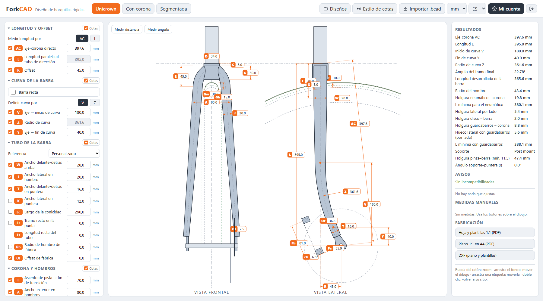
Designing a unicrown fork comes down to three sets of numbers: length and offset (L or AC, plus R), the shoulder shape in the front view (A, E, J, G) and the blade bend in the side view, defined by V or Z, plus Y. From those you get what you need to build it: the developed length of each blade, the bend dimensions, the shoulder radius, the blade-to-steerer mitering and the wheel clearance.
A unicrown has no separate crown. The two blades bend inward at the shoulder and join the steerer directly.
Reference points before you measure
Every dimension uses the same conventions. Mix references and the numbers will not match the drawing.
- Origin: the face of the crown race seat, where the lower bearing sits. L is measured from there.
- Centreline: each blade is defined by its centreline.
- Sections: W, T and J are measured perpendicular to the tube axis.
Side view dimensions: length, offset and blade sections
The side view sets where the axle sits relative to the steerer and what the blade looks like in profile. The names below are the ones used in ForkCAD's panel.
| Dimension | Name in ForkCAD | What it measures |
|---|---|---|
| L | Length parallel to steerer | Crown race seat to axle, measured parallel to the steerer (mm) |
| AC | Axle-to-crown (direct) | The same length measured in a straight line; L = √(AC² − R²) (mm) |
| R | Offset | Offset (rake) of the axle from the steerer axis (mm) |
| F | Race seat → end of transition | To the end of the blade's upper transition (mm) |
| W | Fore-aft width at top | Blade section at the end of F (mm) |
| T | Fore-aft width at dropout | Blade section at the dropout (mm) |
| V, Y, Z | Axle → bend start, Axle → bend end, Bend radius | The blade bend, covered below (mm) |
L and AC are two ways of stating the same length: with one of them and the offset you get the other. The panel lets you pick with “Measure length as”. For the full difference, see how to measure fork axle-to-crown length.
Front view dimensions: shoulder and steerer
The front view defines the shoulder: how far the blades spread, at what height and how they reach the steerer.
| Dimension | Name in ForkCAD | What it measures |
|---|---|---|
| D | Steerer / race seat Ø | Crown race seat diameter (mm) |
| C | Race seat → crown | Crown race seat to crown (mm) |
| A | Outer width at shoulders | Outside width across the shoulders, at height E (mm) |
| E | Shoulder height | Height of the shoulder (mm) |
| J | Lateral width at shoulder | Lateral width of the blade (mm) |
| G | Crown → steerer bottom | From the top down to the lower arch (mm) |
These dimensions depend on each other. If they cannot form a real shoulder, ForkCAD flags them in red with “Inconsistent shoulder shape (check A, J, E, G)”. It does not change your values on its own: you decide which one to adjust.
The blade bend in three sections: V, Y and Z
A curved blade is described in three sections: a straight section parallel to the steerer, an arc, and a lower straight section down to the dropout. Three dimensions define it:
- V (Axle → bend start): height from the axle to where the arc begins.
- Y (Axle → bend end): height from the axle to where the arc ends.
- Z (Bend radius): radius of the arc.
The three are not independent. Under “Define bend by” you enter V or Z, plus Y, and the missing one is calculated. If the radius is what you have fixed, enter Z; if you want to control where the bend starts, enter V. With “Straight blade”, the blade has no bend.
Combinations that do not work
- V must be above Y.
- The bend cannot start inside the upper transition (F).
- If no bend works with the values you entered, ForkCAD warns you.
Shoulder radius and factory-bent blades
The shoulder radius is the bend the blade takes in the front view to reach the steerer. If you bend the shoulder yourself, it is one more output. If the blade comes bent from the factory, the radius is already set and it fixes dimension E: with a given radius, shoulder height is no longer free.
For Columbus unicrown blades, the factory radius shown on a drawing is R80, on FBRN16U410DSK and FBRN16U410DSK001. For the other unicrown references, Columbus does not give the radius on its drawings: ask the distributor or measure it on the blade.
ForkCAD's tube catalogue fills in default dimensions for each reference, including the factory shoulder radius where it is known. They are for reference: check them with the manufacturer before building. Everything stays editable and the program warns you when something does not fit: for example, when the shoulder cannot take that radius with the width A you chose, or when the tube is shorter than the developed length you need.
How to build a unicrown fork: the measurements you need
Once the design is closed, these are the numbers that go to the workshop:
| Measurement | What it is for |
|---|---|
| Developed blade length | Centreline length along the straight sections and bends. Add the dropout insertion and you have the tube cut length. |
| Bend dimensions | Start, end, radius and angles of each bend. |
| Shoulder radius | The shoulder bend in the front view. |
| Blade-to-steerer mitering | Top cut of each blade against the steerer and the fork's plane of symmetry. |
| Wheel clearance | Tyre clearance under the crown and between the blades. |
Mitering the blade to the steerer
The top miter is the cut that lets each blade seat on the steerer. ForkCAD gives it as a developed template at 1:1 scale: cut it out, wrap it around the blade end with the base towards the dropout and line up the “top” mark with the outside of the shoulder bend. Dry-fit before brazing or welding.
Tyre and fender clearance
Clearance is checked in two places: under the crown and in the side gap between the blades, against the minimum clearance you set. If the fork takes a fender, ForkCAD also checks its clearance under the crown and between the blades, warns you if it is tight and gives you the minimum L with a fender. More in fork tyre and fender clearance.
Drawing and templates
The build outputs are a dimensioned 2D drawing to print at 1:1 in PDF and DXF, the developed miter templates, and cut lengths and bend dimensions. If you have not settled on the fork type yet, unicrown vs crowned vs segmented fork compares the three constructions.
FAQ
What is the difference between L and AC on a unicrown fork?
Both measure the length from the crown race seat to the axle. L runs parallel to the steerer and AC in a straight line. They are related through the offset: L = √(AC² − R²).
What shoulder radius do Columbus unicrown blades have?
Columbus gives R80 on the drawing of FBRN16U410DSK and FBRN16U410DSK001. For the other references, Columbus does not give the radius on its drawings. The R1 dimension shown on them is the length of the curved section, not a radius.
Why do you only enter two of V, Y and Z?
Because two of them define the bend: you enter V or Z, plus Y, and the third is calculated. V must be above Y, and the bend cannot start inside F.
Can I open a unicrown designed in BikeCAD in ForkCAD?
Yes, with “Import .bcad”. After importing, review the dimensions and define the blade bend (V or Z, plus Y).
Sources
- Columbus, drawing of the FBRN16U410DSK and FBRN16U410DSK001 blades (factory bend radius R80). Manufacturer documentation, no public link.